
 EN
 AR
 DA
 NL
 FI
 FR
 DE
 EL
 HI
 IT
 JA
 KO
 NO
 PL
 PT
 RO
 RU
 ES
 SV
 TL
 IW
 ID
 SR
 VI
 HU
 TH
 TR
 FA
 MS
 IS
 AZ
 UR
 BN
 HA
 LO
 MR
 MN
 PA
 MY
 SD
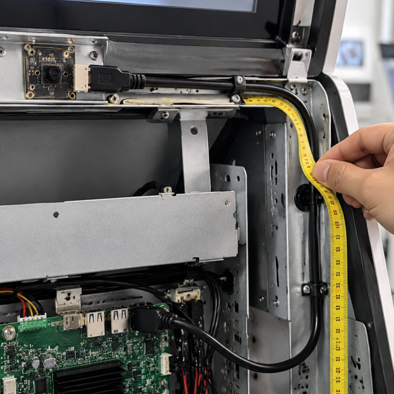
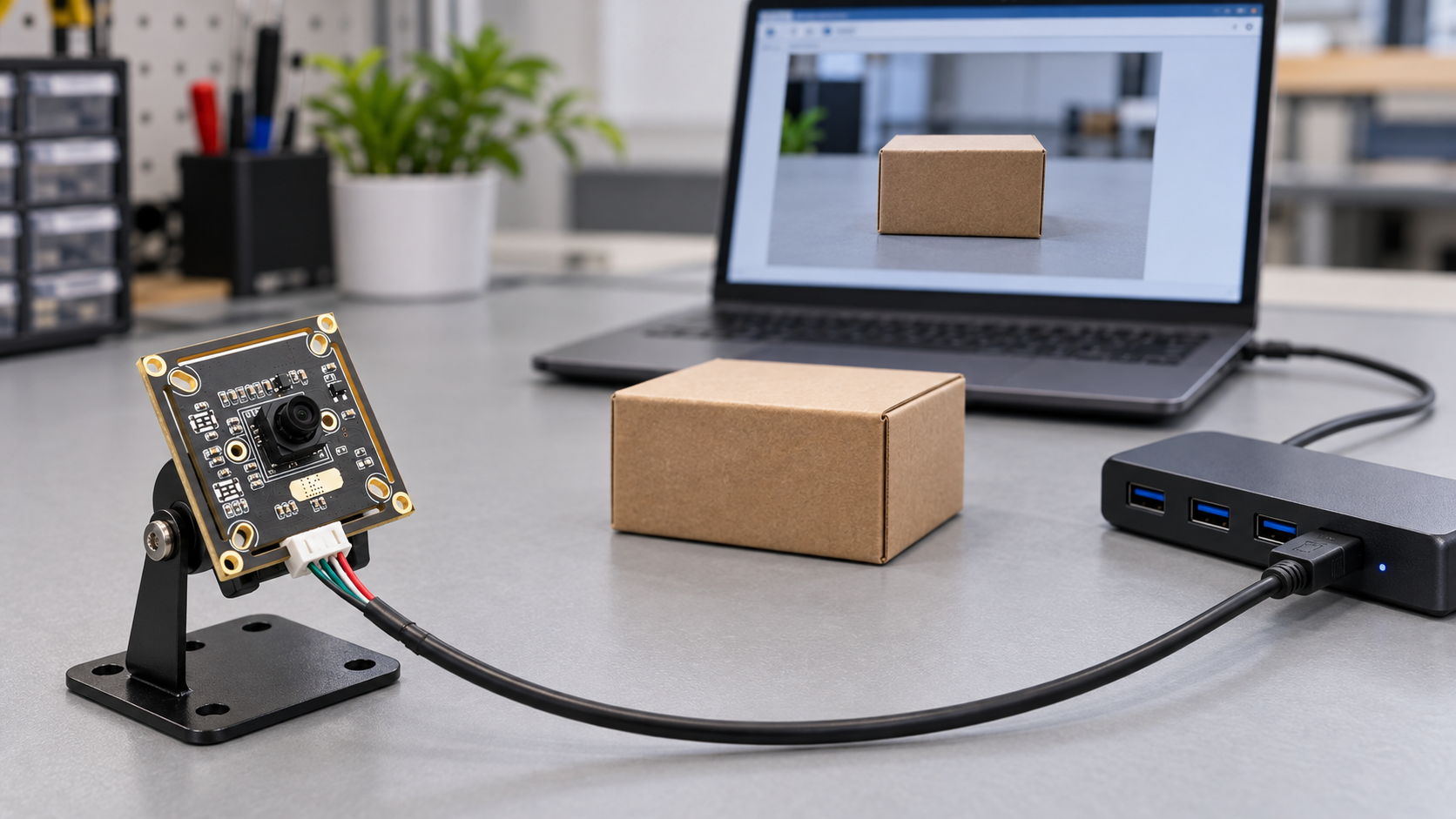
In a self-service terminal, the camera may sit above the display while the motherboard is installed at the bottom of the cabinet. The cable has to run around brackets, pass through internal panels, and sometimes connect through a USB hub. That arrangement is quite different from a short, direct connection on a development bench.
If video starts stuttering, the camera disconnects, or the host fails to detect it after installation, trace the complete connection path before replacing the camera. Changes to cables, adapters, power supplies, or host ports all deserve attention. Defining these requirements when sourcing USB camera modules can reduce the need to dismantle and troubleshoot the finished equipment later.
Measure the Actual Cable Route
Measure along the intended route inside the enclosure, rather than using the straight-line distance between the camera and motherboard. Allow for bends, mounting points, and access during servicing. A moving door or panel may also put tension on the cable.
Leave any extra length where it can be secured. A cable that is too short can pull on the module connector; an unnecessarily long one is harder to manage and may become trapped between the enclosure and a bracket.
Give the supplier the following details:
- Required cable length along the actual route
- Connector types at both ends
- Cable exit direction
- Mounting and cable retention method
- Expected vibration during operation
- Whether the cable will undergo repeated bending
For equipment with moving parts or vibration, include these conditions in the specification or request for quotation. They should not remain informal discussion points.
Specify Tested Conditions Rather Than a Distance Alone
The usable cable length depends on the operating speed, cable construction, connectors, and host hardware. A USB 2.0 or USB 3.0 label alone does not establish whether a particular cable will work reliably in the finished device.
For USB 3.x, Teledyne’s cable documentation notes that the standard does not specify a universal maximum cable length. A supplier’s recommended distance should therefore refer to a specific cable and set of operating conditions.
A useful question to ask is: Has this module been tested for sustained capture with this cable at the required resolution, frame rate, and output format?
For example, when evaluating an IMX298 USB 2.0 camera module, request validation with the intended cable and host rather than assuming compatibility from the interface specification.
If a longer connection requires an active extension solution, assess that solution and its power requirements separately. Ask for the test conditions and supporting documentation, not just a quoted distance.
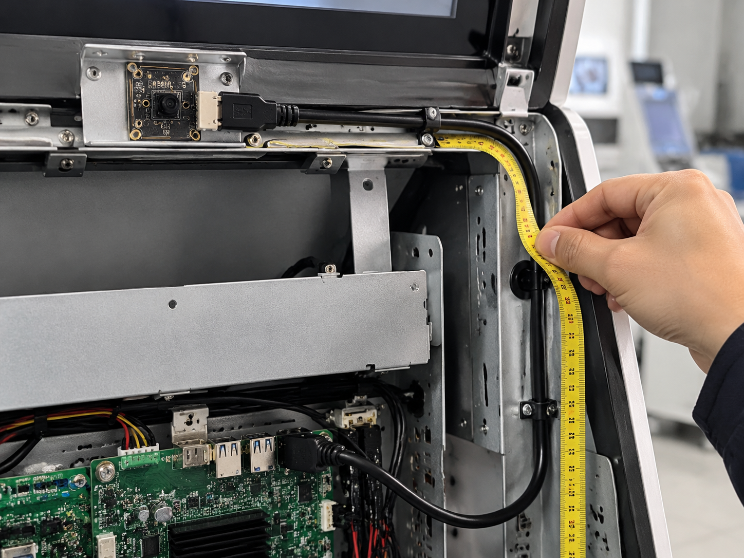
Change One Variable at a Time When Troubleshooting
Start by restoring the short, direct connection that previously worked. Keep the software and capture settings unchanged. Then introduce the longer cable, adapters, and hub one at a time, recording when the problem first appears.
Check power at the camera module. A host port supplying power does not establish that the voltage reaching the module remains adequate during startup and sustained capture. Cable and contact resistance can cause voltage drop under load. These measurements should be carried out by an engineer.
Temporarily reducing the resolution or frame rate can also help narrow the investigation. If the problem disappears at a lower load, however, that does not prove the cable is defective. Host processing load, bandwidth allocation, and driver behavior may also affect the result.
Assess Hub Power and Bandwidth Separately
A USB hub adds ports, but it does not give every connected device an independent connection to the host. Cameras operating through the same upstream link share its available bandwidth, as explained in Teledyne’s USB system guide.
A separately powered hub can address some power limitations, but it does not increase upstream bandwidth. Check both the per-port power capability and the hub’s total power budget. The supplied power adapter must also support the intended combination of devices running together.
Test that complete combination. If barcode scanners or storage devices share the hub, operate them alongside the cameras. Different physical USB ports on the host may also share internal resources, so port count alone is not a reliable measure of available bandwidth.
Validate With the Intended Production Configuration
Use the cables, hub, power supply, and host planned for production, rather than temporary substitutes. Keep the resolution, frame rate, and output format consistent so that test results can be compared.
In addition to sustained capture, check:
- Camera detection at system startup
- Repeated capture start and stop cycles
- Recovery after a power cycle
- Sleep and wake behavior, where required
- Whether capture recovers after a fault or requires manual reconnection
Record the actual frame rate, dropped frames, disconnections, and relevant software logs. Set the test duration according to the equipment’s expected operating cycle. A brief, clean preview does not replace system-level validation, particularly for unattended equipment where recovery matters.
Operating-system compatibility should also be checked on the intended platform. Our guide to sourcing a multi-OS USB camera module for kiosks and terminals covers that part of the selection process.
Give the Supplier Enough Information to Reproduce the Issue
When reporting a problem, include a connection diagram, module model, cable length, hub model, and power supply model. State the operating system, capture software, and conditions under which the fault occurs.
Share these details when you contact Sinoseen about your camera integration. They give the engineering team a more useful starting point than a description such as “the image is unstable.”
Once validation is complete, retain a record of the approved configuration. If the cable or hub changes later, repeat the relevant tests. Similar appearance does not establish equivalent performance.
Frequently Asked Questions
Q1:Is a Separately Powered USB Hub Always the Better Choice?
The choice depends on the total device load, per-port power capability, and bandwidth requirements. An external power supply alone does not guarantee reliable operation.
Q2:Can Standard USB Extension Cables Be Used in Production?
The specific cable and complete connection arrangement need to be validated. Also confirm that the supplier can maintain consistent cable specifications across production batches.
Q3:Why Do Two Cameras Work Individually but Fail When Used Together?
Check shared bandwidth, total power demand, and host processing capacity first. Keep logs from the period when both cameras are running, since individual tests may not reveal the limitation.
Q4:When Should the Cable Specification Be Finalized?
Once the mounting positions and motherboard layout are reasonably clear, include the intended cable length in prototype testing. Do not wait until the enclosure design is finalized to validate the connection.
Table of Contents
- Measure the Actual Cable Route
- Specify Tested Conditions Rather Than a Distance Alone
- Change One Variable at a Time When Troubleshooting
- Assess Hub Power and Bandwidth Separately
- Validate With the Intended Production Configuration
- Give the Supplier Enough Information to Reproduce the Issue
- Frequently Asked Questions