
 EN
 AR
 DA
 NL
 FI
 FR
 DE
 EL
 HI
 IT
 JA
 KO
 NO
 PL
 PT
 RO
 RU
 ES
 SV
 TL
 IW
 ID
 SR
 VI
 HU
 TH
 TR
 FA
 MS
 IS
 AZ
 UR
 BN
 HA
 LO
 MR
 MN
 PA
 MY
 SD
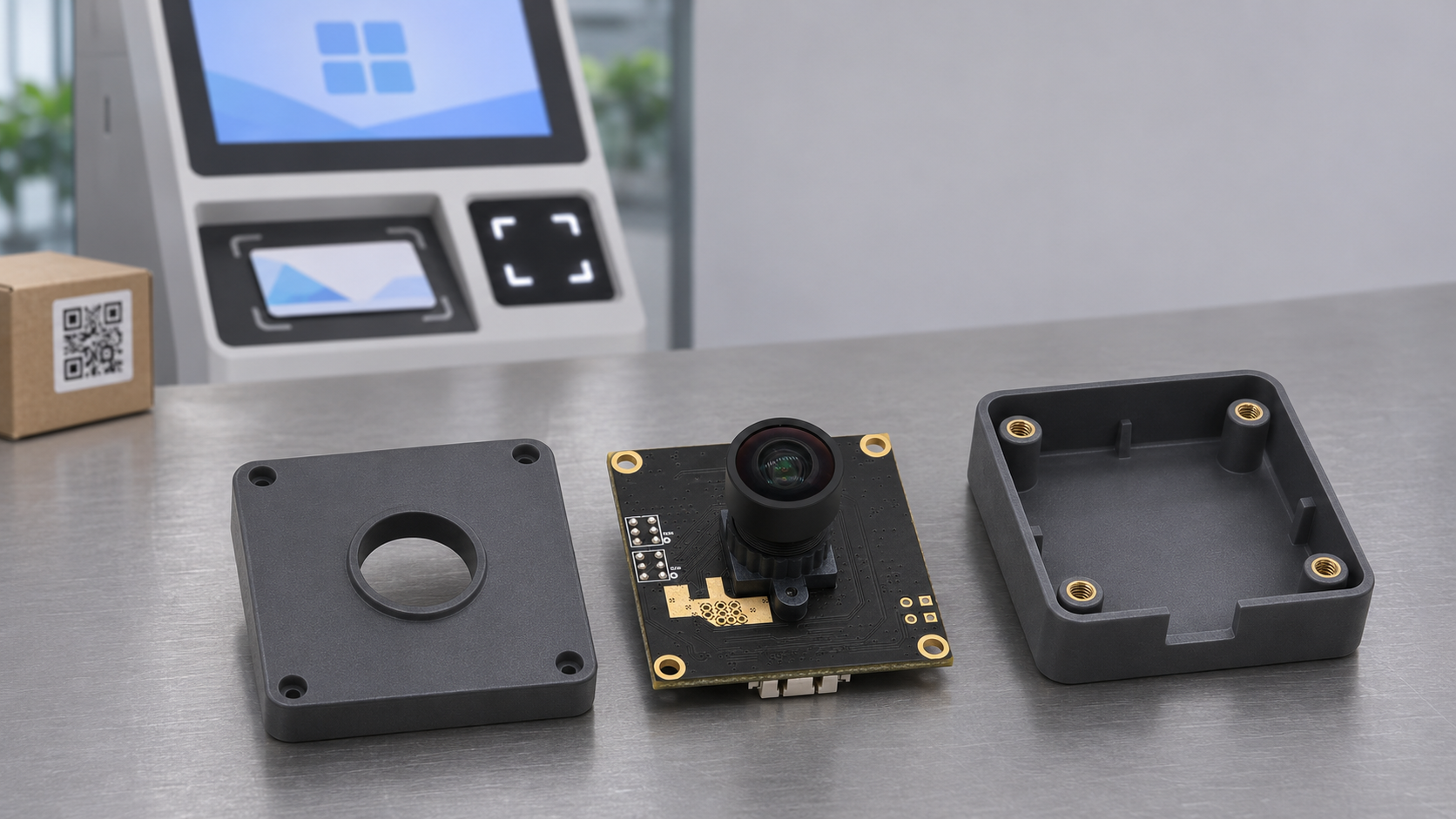
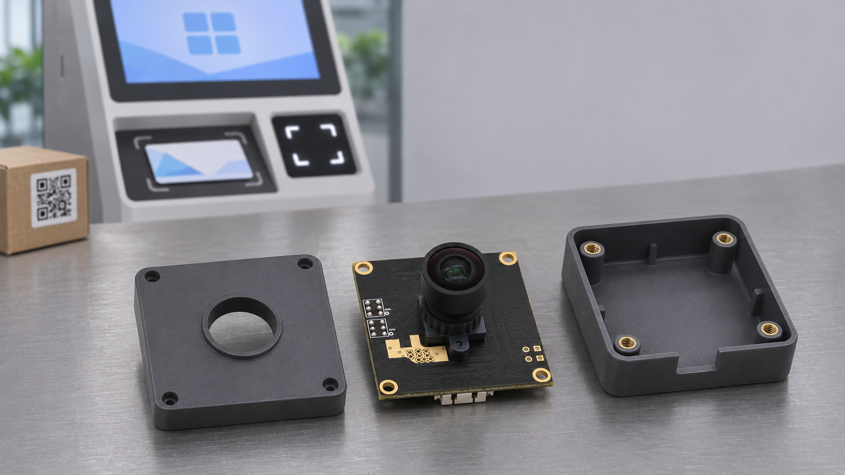
A camera may read labels easily on a development bench, yet become difficult to use once installed in a scanning terminal. Move the label closer, and its edges fall outside the image. Move it farther away, and small text or dense QR codes lose detail. Even with the same lens, recessing the camera farther behind the front panel can introduce dark corners if the opening blocks part of the view.
These symptoms warrant checking the field of view, working distance, and mechanical layout together before assuming a sensor fault. When customizing a USB camera module, begin with what the device needs to capture, where the target will be, and how the camera will be mounted. Those details give the supplier a practical basis for selecting the lens and reviewing the housing.
Define the Target Area Before Choosing the Lens Angle
“We need a wide-angle lens” leaves several important questions unanswered. The supplier needs the target dimensions, its distance from the camera, and the amount of variation allowed in its position.
For document capture, the image must include the entire document with enough margin for imperfect placement. If the field of view matches the document dimensions too closely, a slight rotation can cut off text or security features near the edges.
Barcode applications also require the physical size of the smallest code element, such as a narrow bar or an individual QR code cell. This helps establish how much image detail the system needs to resolve.
At a fixed output resolution, a wider field of view generally assigns fewer pixels to a target of the same physical size. A very wide view may cover the whole operating area while leaving too few pixels across a small code for reliable decoding.
Choose camera module lenses around the capture task rather than the widest available angle. Edmund Optics’ imaging fundamentals likewise treats field of view, working distance, and resolution as related selection criteria.
Specify the Direction and Operating Mode of the Field of View
A specification stating “90° FOV” may refer to the horizontal, vertical, or diagonal angle. These are different measurements. Designing around a 90° horizontal view when the specification actually describes the diagonal can leave less horizontal coverage than expected.
Ask the supplier to identify:
- Horizontal field of view, or HFOV
- Vertical field of view, or VFOV
- Diagonal field of view, or DFOV
- The sensor and output mode used for those specifications
Output modes also deserve attention. Some modules produce a lower-resolution image by cropping the center of the sensor rather than scaling the full image. In that case, the effective field of view becomes narrower.
For acceptance testing, a requirement such as “cover this width and height at this working distance” is often easier to verify than an angle alone.
Include the Full Operating Distance Range
Working distance is normally measured from the front of the lens to the target, rather than from the housing panel or PCB. Mark the measurement reference on the drawing so that the mechanical designer and lens supplier use the same starting point.
If users hold a QR code in front of the terminal, specify the nearest and farthest expected positions. A fixed-focus module needs to meet the reading requirement across that range, not just at the distance where the image looks sharpest.
Test the same target at the near, typical, and far positions. Check both coverage and readable detail, then move the target toward the image edges. This can reveal problems that remain hidden when every test is performed at the center of the frame.
Check the Housing Opening Against the Optical Path
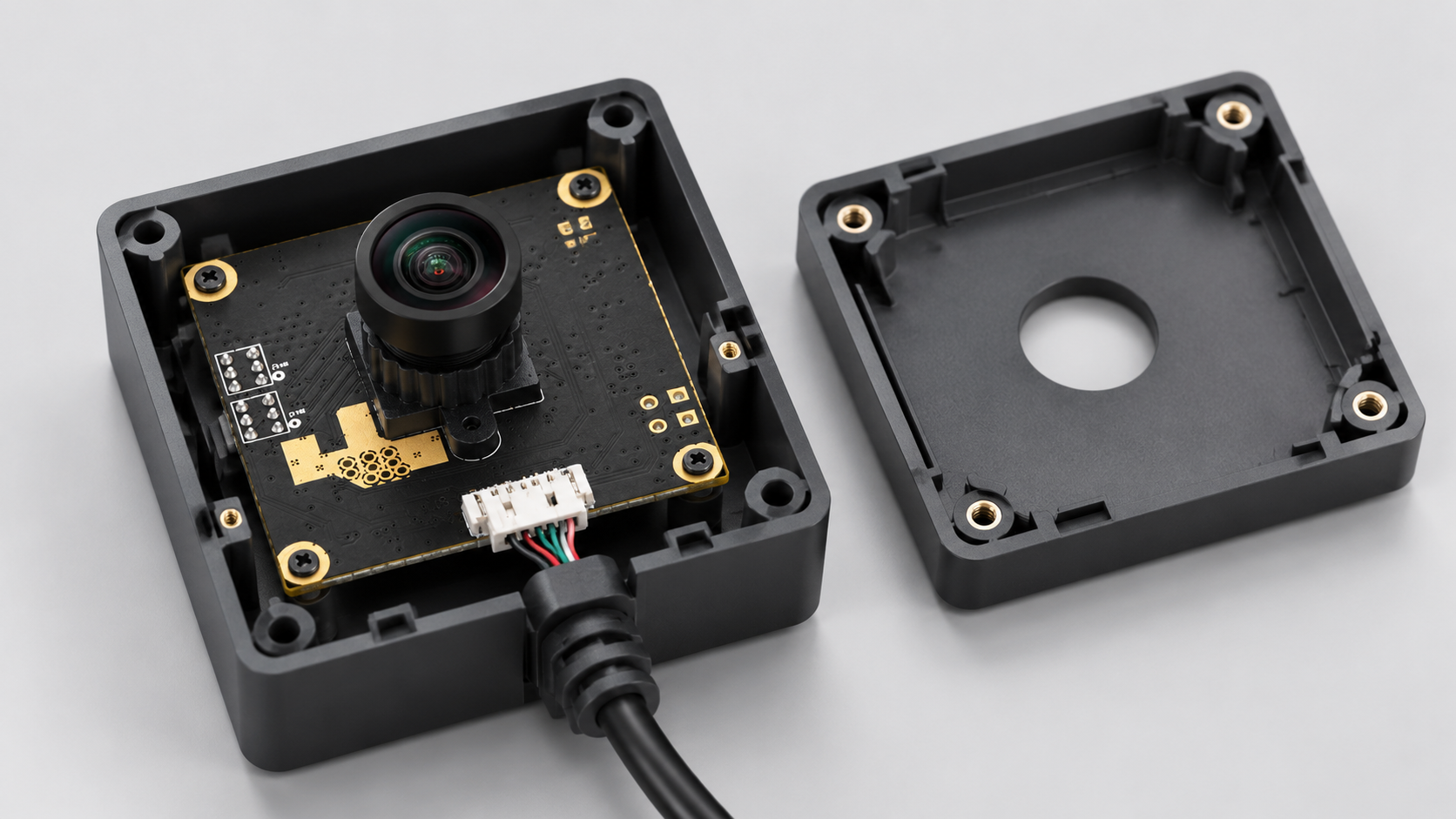
The required opening cannot be determined from the lens barrel diameter alone. Panel thickness, lens recess depth, and viewing angle all affect whether the opening obstructs incoming light.
A thick panel or deeply recessed lens increases the risk of the opening walls blocking light from the edges of the field. The result may be dark corners or visible black borders. Provide a drawing showing the lens position relative to the panel so the supplier can assess the clearance for the selected optics.
Install the actual panel during prototype testing. If the design includes a protective window, fit that as well and check for reflections, contamination, and changes in sharpness.
Dark image edges do not always indicate an obstructed opening. The lens itself can produce illumination falloff, so distinguish optical shading from mechanical blockage before changing the housing.
Leave Room for Assembly and Servicing
PCB length and width describe only part of the space required. Check lens protrusion, mounting-hole locations, screw access, and the orientation of the USB connector.
A module may fit inside the enclosure while leaving too little room to insert the plug or bend the cable safely. Where the lens requires focus adjustment during assembly, allow access for adjustment and locking. Tightening the mounting bracket should not bend the PCB or shift the camera’s orientation.
Define dust and water protection requirements for the complete assembly. A bare module’s specifications do not establish the protection level of the finished enclosure.
Validate the Final Assembly
When discussing OEM camera module requirements, provide sample targets and their dimensions, the working distance range, the required coverage, and the intended output mode. Include drawings of the housing opening and camera mounting position.
Use the lens, bracket, protective window, and housing intended for production during acceptance testing. Capture images under the expected lighting conditions. Along with full-frame images, record recognition results when the target is near an edge, tilted, or presented at different distances.
Include these conditions in the acceptance criteria. They give both parties a clear basis for retesting if the lens changes or the housing is revised.
To discuss a specific design, send Sinoseen your camera integration requirements, including the optical and mechanical constraints together.
Frequently Asked Questions
Is a Wide-Angle Lens Always Better for Barcode Scanning?
No. At the same output resolution and working distance, a wider view generally leaves fewer pixels across a code of a given size. Lens distortion may also affect features near the edges. Check the detail available in the smallest code before choosing the field of view.
Does Changing the USB Output Resolution Change the Field of View?
It depends on how the module generates that output. Scaling the full image generally preserves the field of view, while cropping the sensor’s central area narrows it. Confirm the result in the intended capture mode.
Can a Fixed-Focus Module Work at Different Distances?
It can provide acceptable results over a limited range. The usable range depends on the optics, lighting, and recognition requirements. Test the nearest, typical, and farthest target positions before approving the configuration.
Should the Housing Be Designed After the Camera Module Is Selected?
Optical and mechanical design should proceed together. Lens position, opening size, and connector clearance affect one another. Checking them early reduces the risk of discovering obstruction or assembly problems after the housing tooling has been completed.
Table of Contents
- Define the Target Area Before Choosing the Lens Angle
- Specify the Direction and Operating Mode of the Field of View
- Include the Full Operating Distance Range
- Check the Housing Opening Against the Optical Path
- Leave Room for Assembly and Servicing
- Validate the Final Assembly
- Frequently Asked Questions