 EN
EN
 AR
AR
 DA
DA
 NL
NL
 FI
FI
 FR
FR
 DE
DE
 EL
EL
 HI
HI
 IT
IT
 JA
JA
 KO
KO
 NO
NO
 PL
PL
 PT
PT
 RO
RO
 RU
RU
 ES
ES
 SV
SV
 TL
TL
 IW
IW
 ID
ID
 SR
SR
 VI
VI
 HU
HU
 TH
TH
 TR
TR
 FA
FA
 MS
MS
 IS
IS
 AZ
AZ
 UR
UR
 BN
BN
 HA
HA
 LO
LO
 MR
MR
 MN
MN
 PA
PA
 MY
MY
 SD
SD

How to Build an Automated Meter Reading Camera System
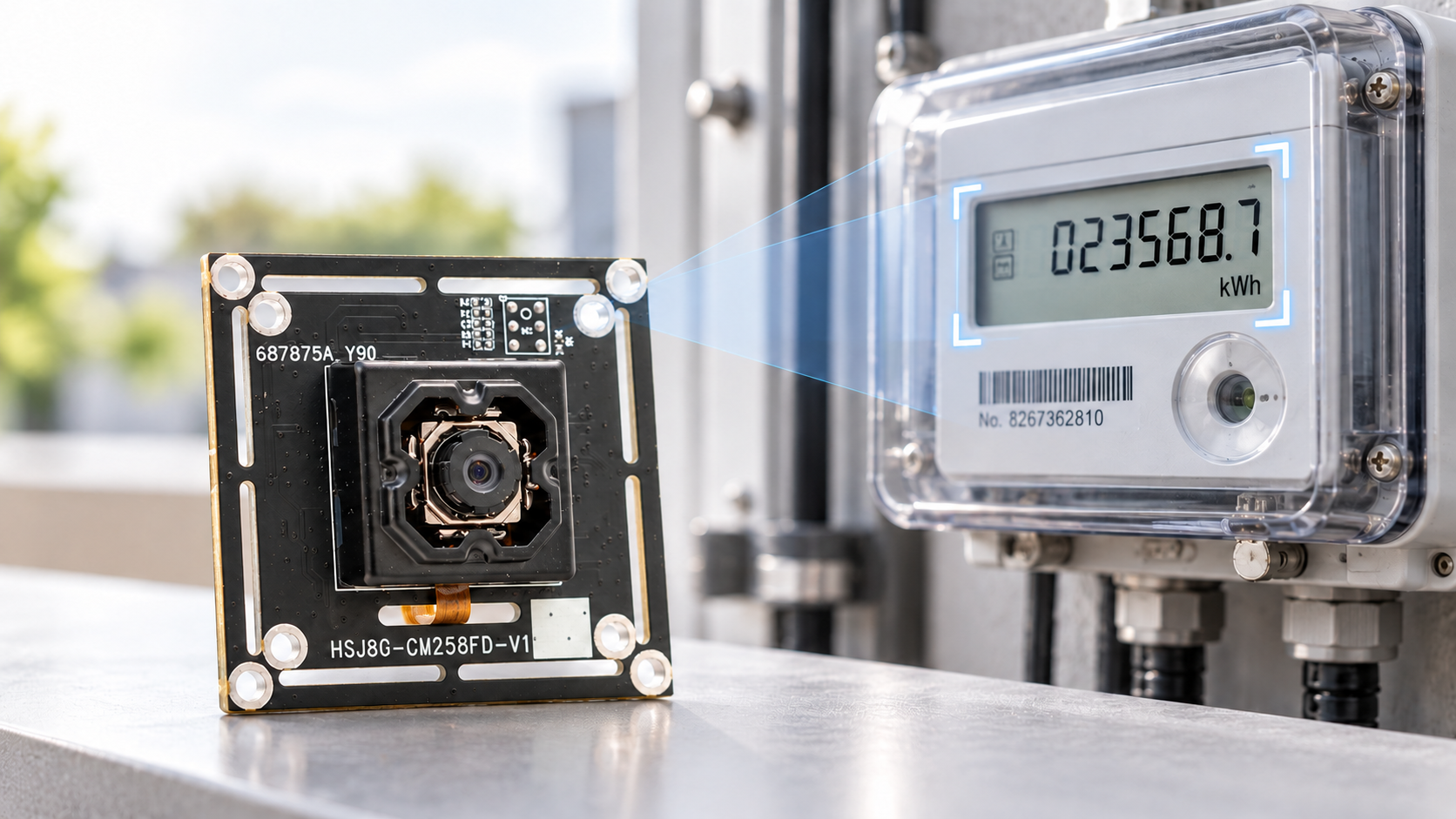
A meter behind a cabinet door can be difficult to photograph. The digits are small, the protective cover reflects light, and a single bright patch can hide the decimal point. Building an automated meter-reading camera system means capturing a clear image every time and assigning each reading to the correct device.
For existing meters without a usable data interface, a camera can capture the display for recognition by a host application.
Define the Reading Task and Handle Uncertain Results
Digital meter reading typically uses OCR, or optical character recognition, to extract text from an image. Reading an analog dial requires determining the position of the pointer relative to the scale. The two tasks need different software processing.
Include decimal points, units, and positive or negative signs in the recognition task. If 12.5 is read as 125, the result is wrong even though every digit has been identified. For multiple meters, assign a separate image region and a fixed identifier to each instrument to prevent readings from being assigned incorrectly. When a reading is uncertain, save the original image and flag it for review rather than automatically filling in a plausible value.
Choosing a Camera Module for Meter Reading
Framing and Focus Determine Which Details Are Visible
Choose the mounting position with the cabinet door in its normal operating position, then select the lens and resolution. A wider field of view captures more of the scene, but at the same output resolution, each character may occupy fewer pixels.
Inspect thin strokes, decimal points, and characters near the edge of the display at the original image size. Digital enlargement cannot recover detail that was never captured. For close-range installations, also confirm the minimum focusing distance. Pixel count alone does not establish suitability.
Adjust Reflections and Exposure on Site
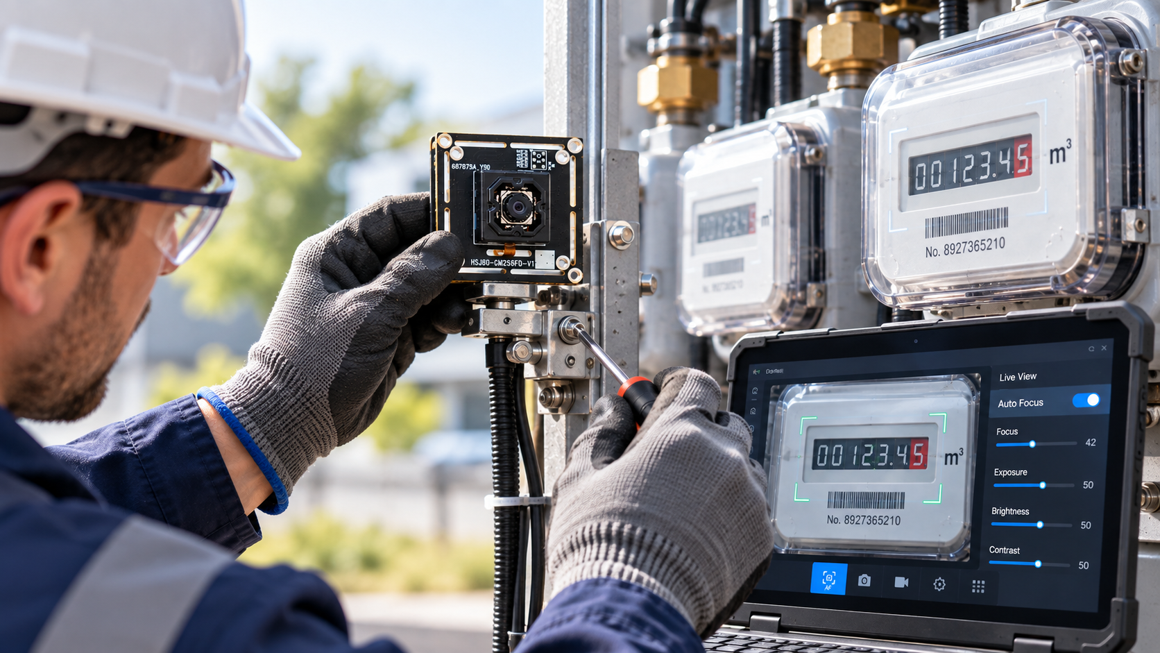
Reflections on the protective cover can obscure character strokes. Try changing the camera angle, moving the light source, or adding diffused illumination. Also check the image with the room lights off and with daylight reaching the meter.
Electronic displays may show bands or missing segments when their refresh timing interacts with the camera exposure. Capture a sequence and inspect it frame by frame. Adjust one condition at a time to identify the cause.
Test the Complete USB Connection
Choosing a USB camera module with a compatible interface is only the starting point. Confirm driver support on the target system and the available combinations of resolution, frame rate, and output format. Test with the final host, cable, and application.
Where the IMX258 USB Module Fits
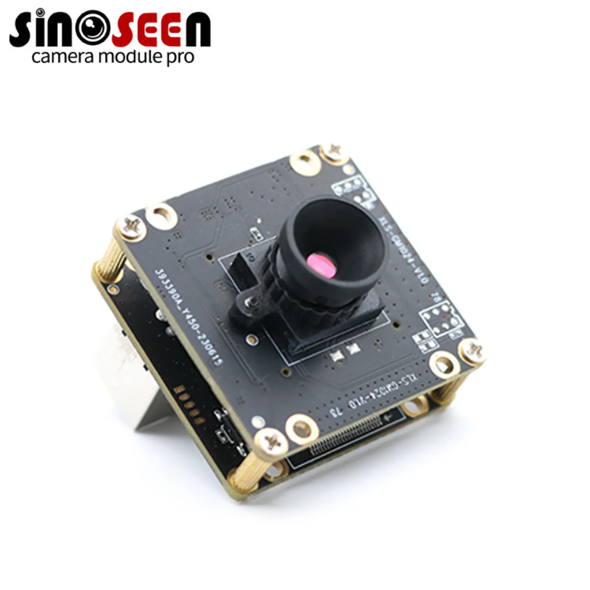
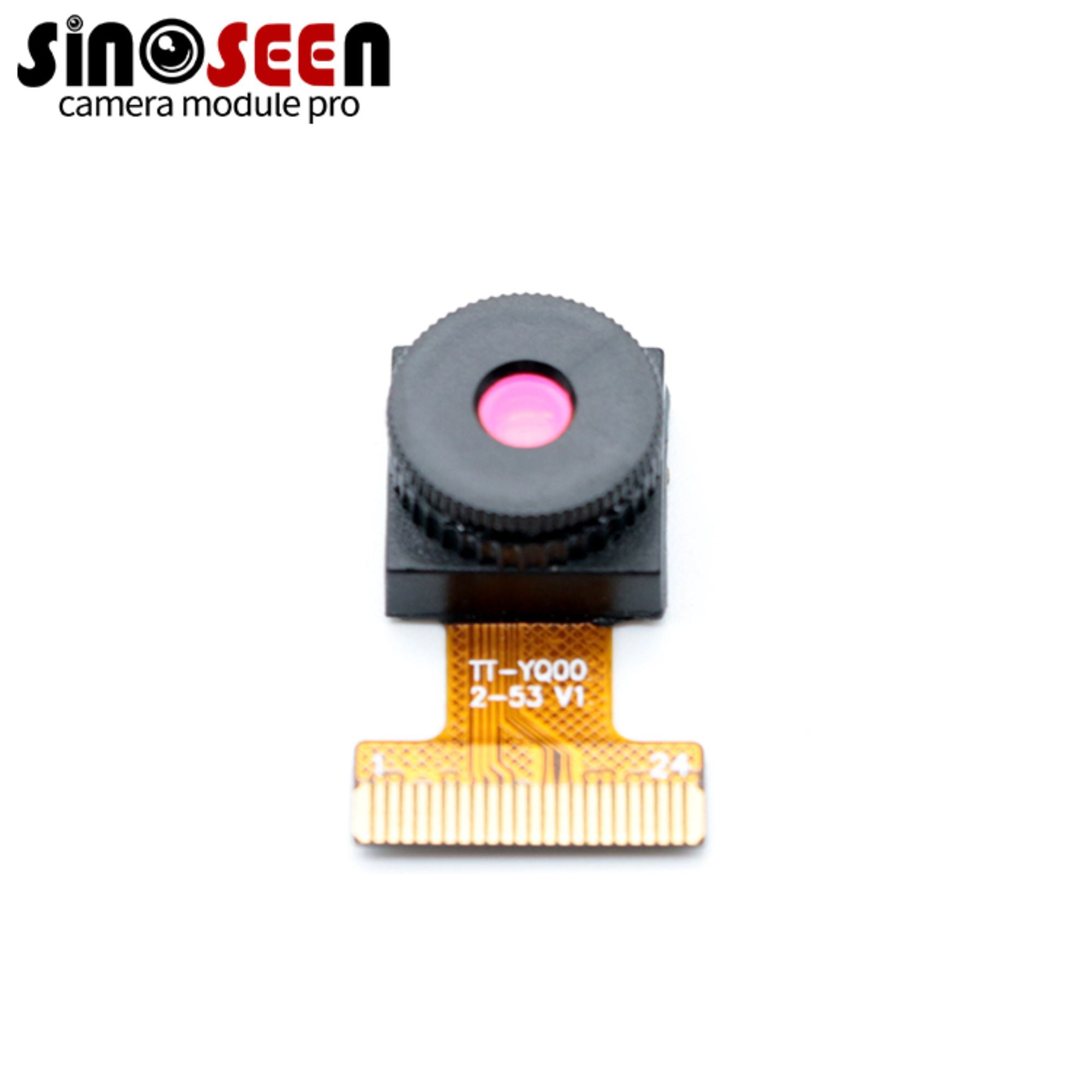
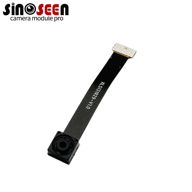
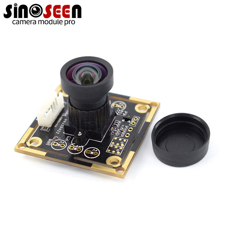
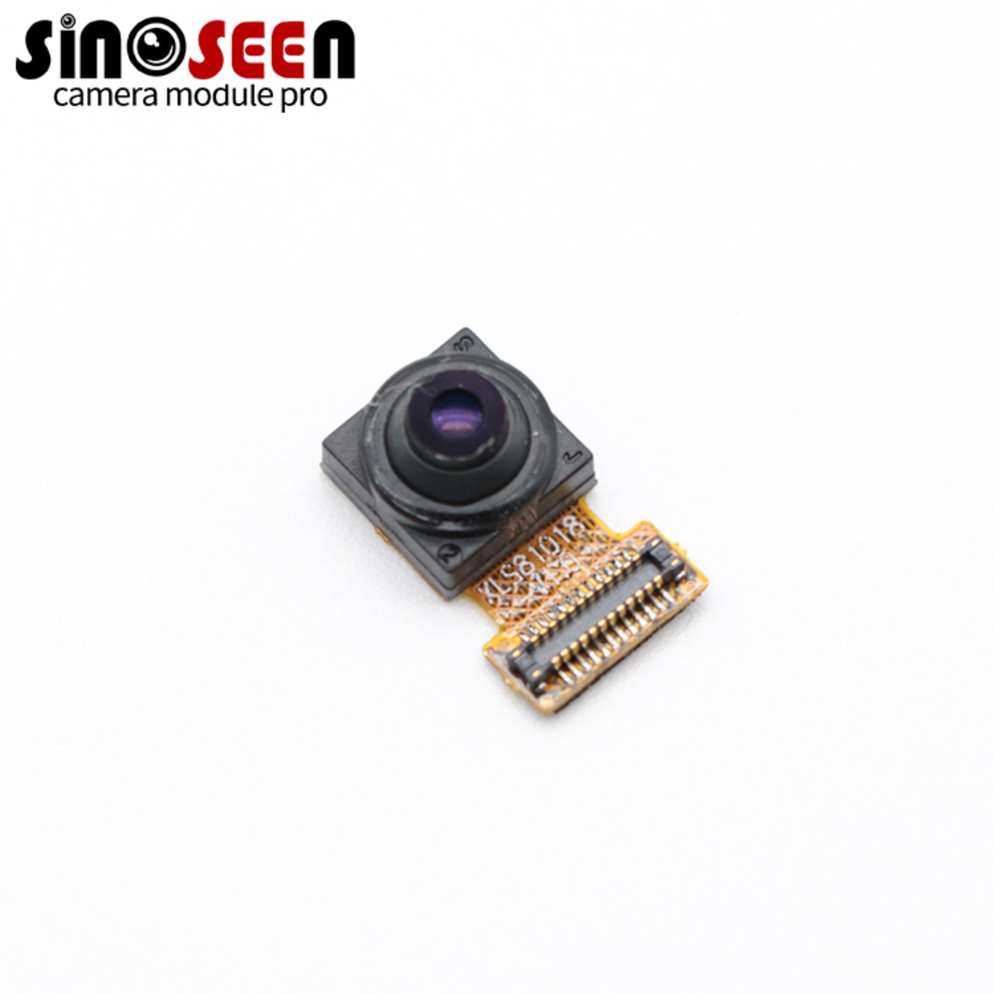
Sinoseen's IMX258 USB camera module, model HSJ80-GM258FD-V1.0, is a candidate for this type of prototype. Its product page lists USB 2.0, autofocus, and a resolution of 4224 × 3144, with an optional 80° field of view.
Higher resolution can help preserve small character details, although the actual USB output modes still need confirmation. An autofocus camera module can simplify setup when mounting distances vary between cabinets. Once installed, confirm that the firmware supports the required focus controls so that reflections or foreground cables do not draw focus away from the display.
Whether an 80° field of view is suitable depends on the working distance and the number of meters in view. When requesting samples, specify the lens configuration, minimum focusing distance, and output modes, then test with the target meter. The camera supplies images; these specifications alone cannot guarantee OCR accuracy.
Moving from Sample Testing to Reliable Operation
A secure bracket holds the framing steady and prevents movement caused by opening the cabinet door or pulling on the cable. After the application starts, allow exposure and focus to settle before accepting images for recognition.
The capture interval depends on how quickly the reading changes. A cumulative meter read every few minutes usually does not require continuous video streaming at the highest resolution.
During validation, save the original image together with the reading, meter identifier, and timestamp. Cover digit transitions, blank displays, typical dust accumulation, USB reconnection, and recovery after a power interruption. Before ordering production units, confirm the approved camera module configuration, including the lens, board revision, cable, and firmware version, and agree on how configuration changes will be communicated.
Frequently Asked Questions
Q1:Can the Camera Read Meter Values Automatically?
The camera captures images. A host application must locate the display, identify the digits or pointer, and validate the result. Test image capture quality and reading accuracy separately.
Q2:Does Every Installation Need Autofocus?
No. A fixed-focus configuration is worth evaluating when the working distance is fixed and installation is consistent. If the distance varies, test whether autofocus can meet the application requirements.
Q3:What Should the First Sample Image Show?
Photograph a real meter in the intended mounting arrangement. Include the complete reading, decimal point, units, and enough surrounding detail to identify the instrument. Keep the original image without cosmetic sharpening.
Q4:Should the Algorithm Be Replaced First When Recognition Fails?
Check the original image first. Glare, poor focus, and too few pixels per character are imaging problems. If the image is clear but the reading is wrong, investigate the recognition and validation logic.