 EN
EN
 AR
AR
 DA
DA
 NL
NL
 FI
FI
 FR
FR
 DE
DE
 EL
EL
 HI
HI
 IT
IT
 JA
JA
 KO
KO
 NO
NO
 PL
PL
 PT
PT
 RO
RO
 RU
RU
 ES
ES
 SV
SV
 TL
TL
 IW
IW
 ID
ID
 SR
SR
 VI
VI
 HU
HU
 TH
TH
 TR
TR
 FA
FA
 MS
MS
 IS
IS
 AZ
AZ
 UR
UR
 BN
BN
 HA
HA
 LO
LO
 MR
MR
 MN
MN
 PA
PA
 MY
MY
 SD
SD

How to Source an Industrial Endoscope Module for Pipe and Weld Inspection
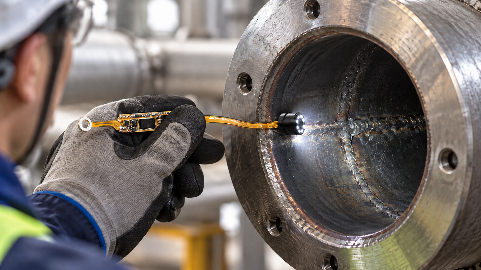
An industrial endoscope module must capture useful images inside a space where the camera, lighting, and viewing angle are difficult to control. Nearby metal walls can reflect the probe light while deeper sections remain dark. Even a small movement can change the image. Manufacturers of handheld inspection equipment should account for these conditions when selecting a module, before the enclosure and electronics are finalized.
Consider visual inspection inside a short pipe after machining. The operator guides the probe to a joint, holds it at a suitable distance, and saves an image for review. When comparing endoscope camera modules, start with this workflow: the assembled probe must fit through the opening, resolve the relevant surface detail, and deliver a stable image to the recording device. This guide focuses on visual inspection, rather than calibrated defect measurement or automatic weld acceptance.
Confirm How the Probe Will Enter the Pipe
Measure the smallest opening along the insertion path, including bends, and allow room to orient the camera toward the inspection area. Sensor size alone does not determine whether the assembled probe will fit. The lens holder, lighting, protective window, cable termination, and housing all occupy space. Ask for a mechanical drawing that includes the rigid length behind the lens, since this can determine whether the probe can pass a bend.
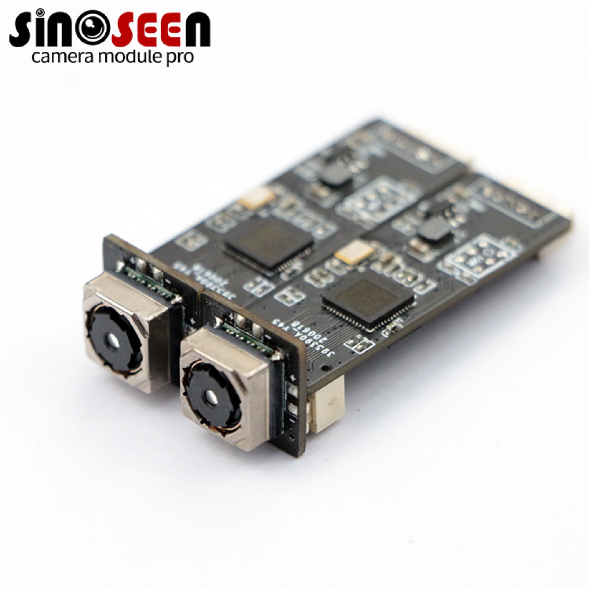
Confirm where the USB processing board will sit. Some designs separate the small camera head from electronics located outside the inspection area. Obtain the sample assembly before committing to a handle design or tooling. Give the supplier a sketch showing the entry point, inspection location, insertion depth, and any sharp edges that may contact the cable. This gives the mechanical and camera teams a shared basis for evaluating the design.
Define the Working Distance Before Choosing the Lens
Working distance is the distance from the lens to the surface being inspected. It can change substantially as the operator advances or rotates the probe. For a fixed-focus design, request sample images of the pipe wall and joint at both the nearest and farthest intended distances. A clear forward-facing image does not prove that a nearby sidewall will also be in focus.
Decide on the viewing direction early. Forward viewing helps guide the probe, while inspecting the circumference of a weld may require an angled view or a different optical arrangement. Discuss this geometry before selecting a wider-angle lens. A wider field of view includes more of the interior, but gives each small feature fewer pixels at the same image resolution. Choose coverage around the detail the operator needs to see.
For a repeatable bench test, secure the probe in a fixture and move a representative surface through the planned working range while keeping image settings unchanged. This makes it easier to identify the usable focus range. Handheld movement and exposure changes can otherwise obscure the reason an image looks soft.
Adjust Illumination Using Real Inspection Surfaces
A desktop demonstration under office lighting will not reveal the main problems inside a pipe. Test the camera in representative pipe sections with the intended illumination. Polished metal can create strong reflections, and increasing brightness may simply enlarge the washed-out area. Adjust light intensity and viewing angle, then check whether the joint and surrounding surface remain visible.
In darker sections, check whether the lighting preserves enough detail during normal handling. A result that depends on holding the probe perfectly still for an extended period may be unsuitable for the intended workflow. Keep the protective window clean: fingerprints or residue near the lens can scatter light and create a hazy image. Record the lighting settings for each sample so that images taken under different conditions are not treated as a direct camera comparison.
Evaluate the OV9734 USB Module as a Prototype Candidate
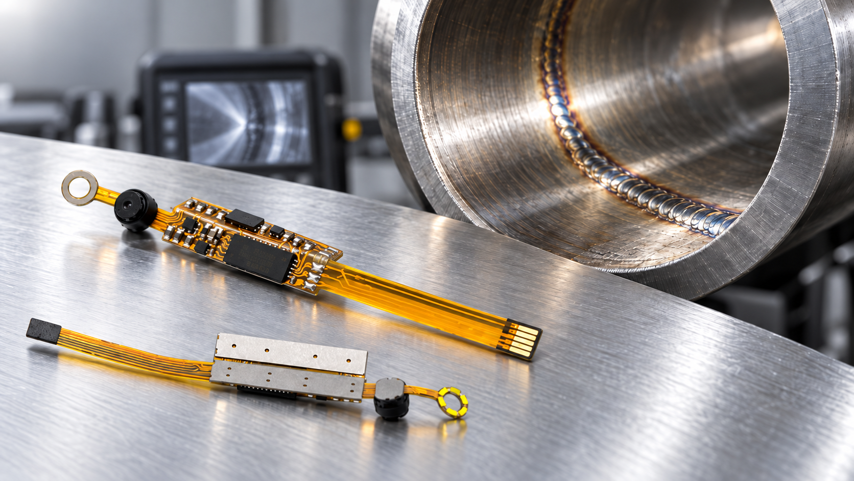
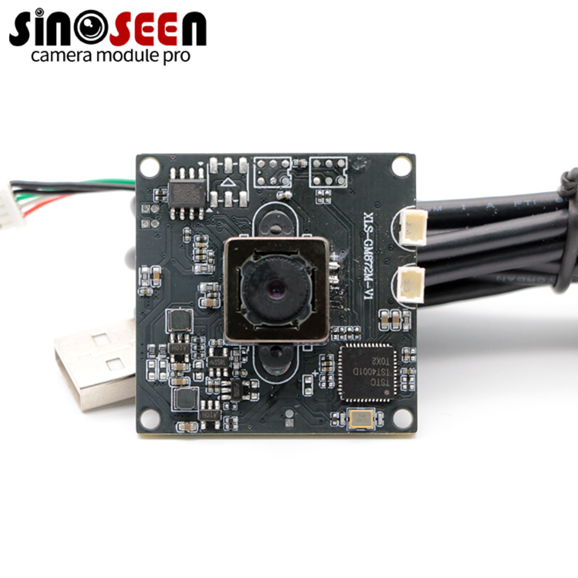
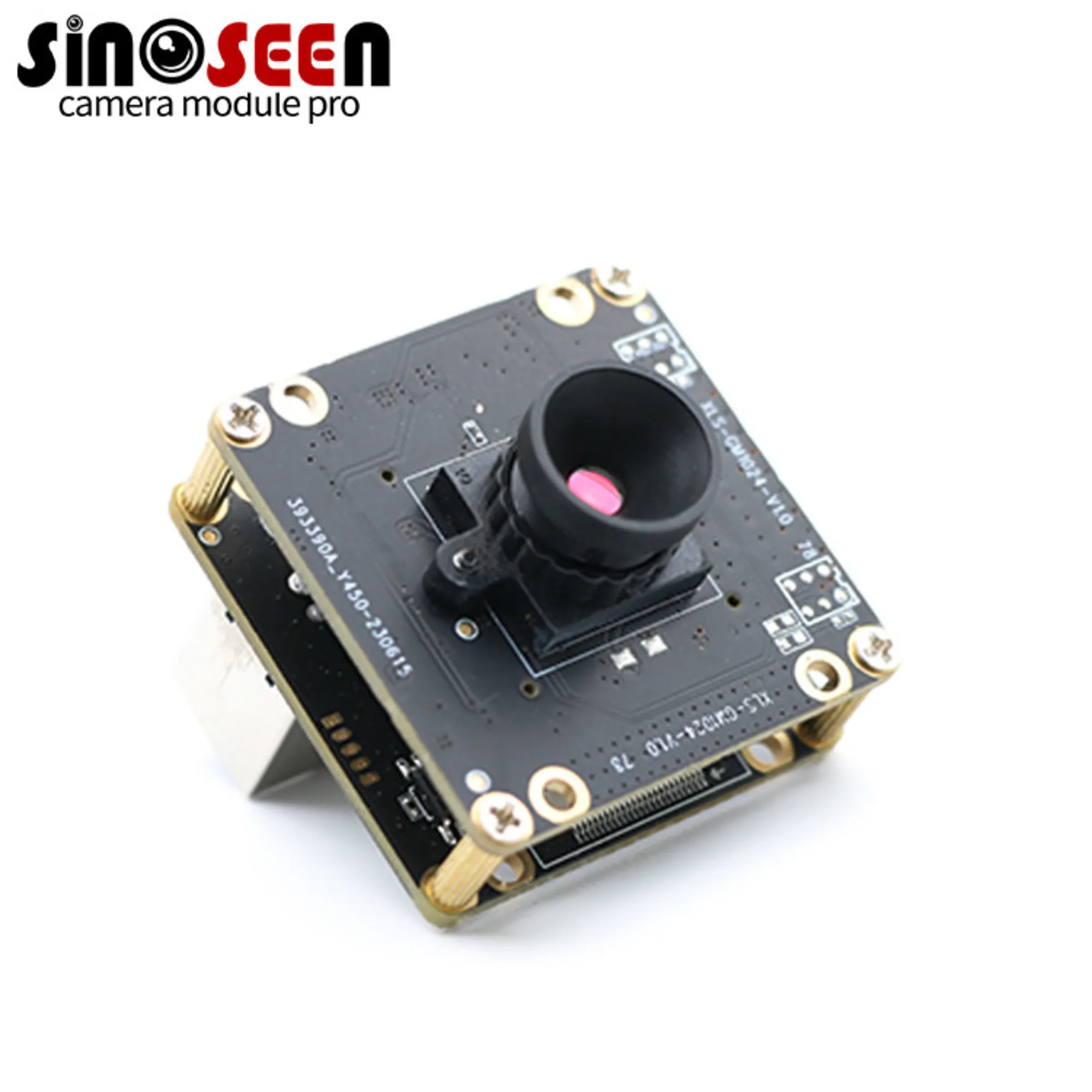
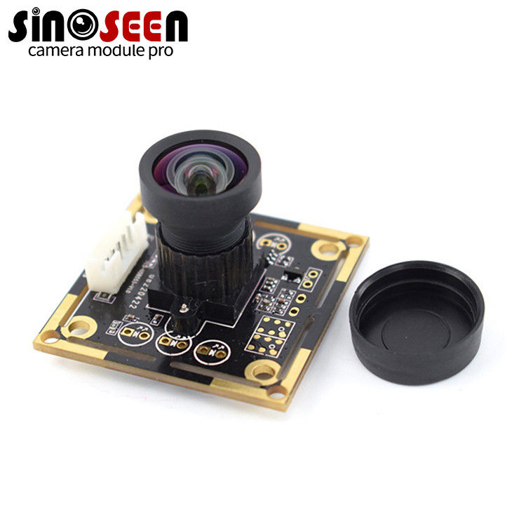
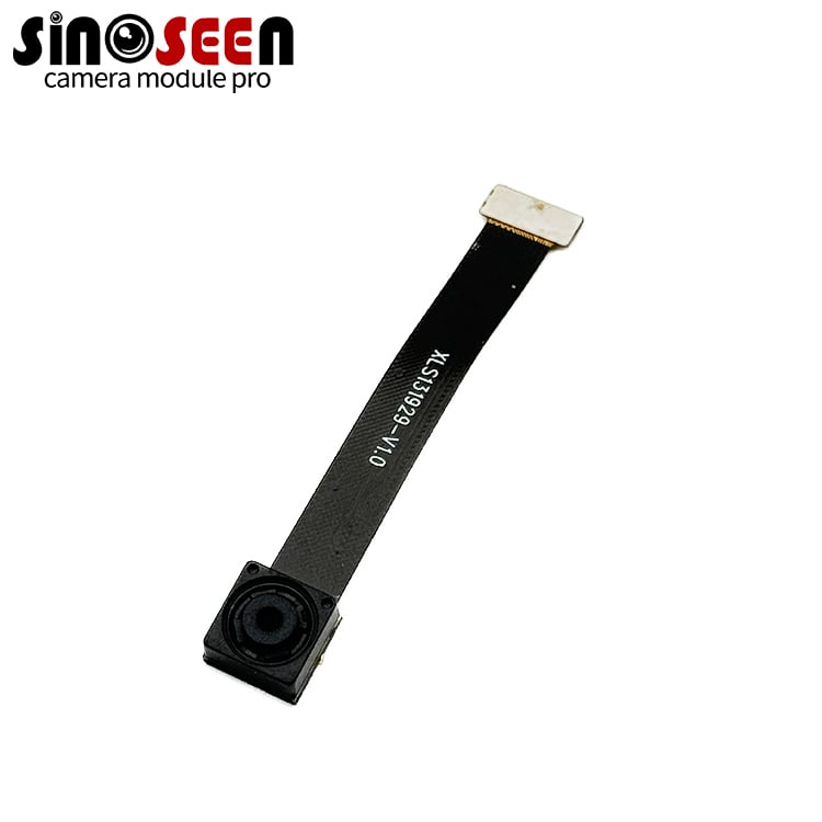
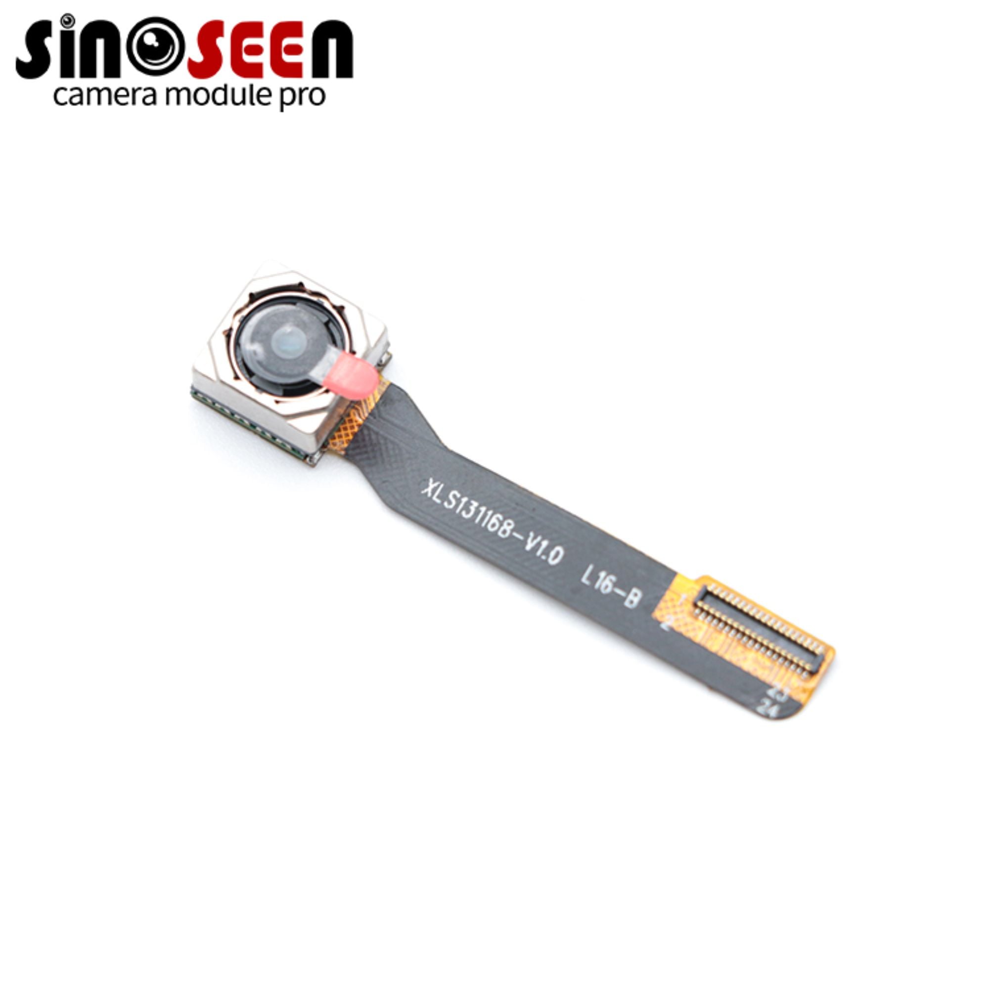
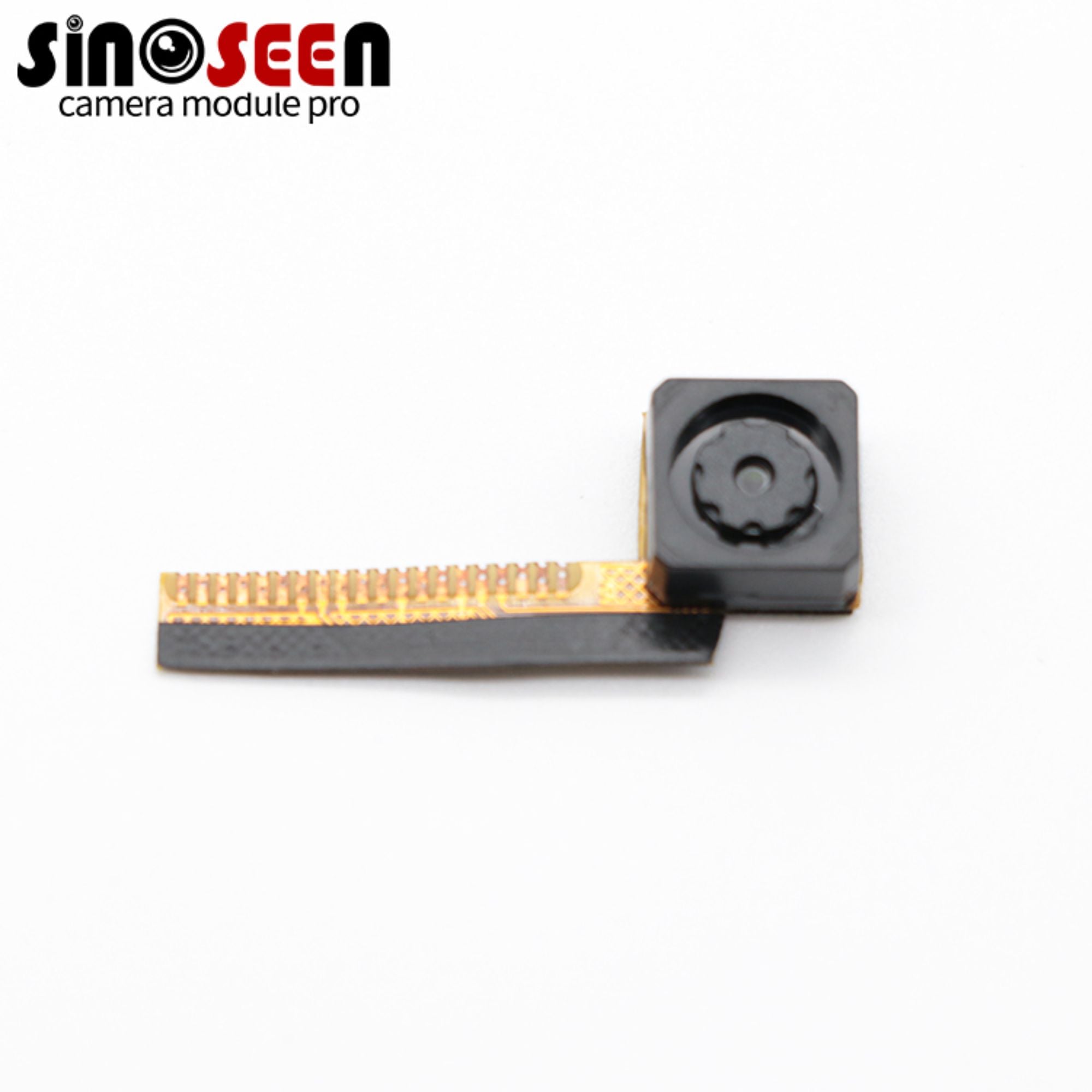
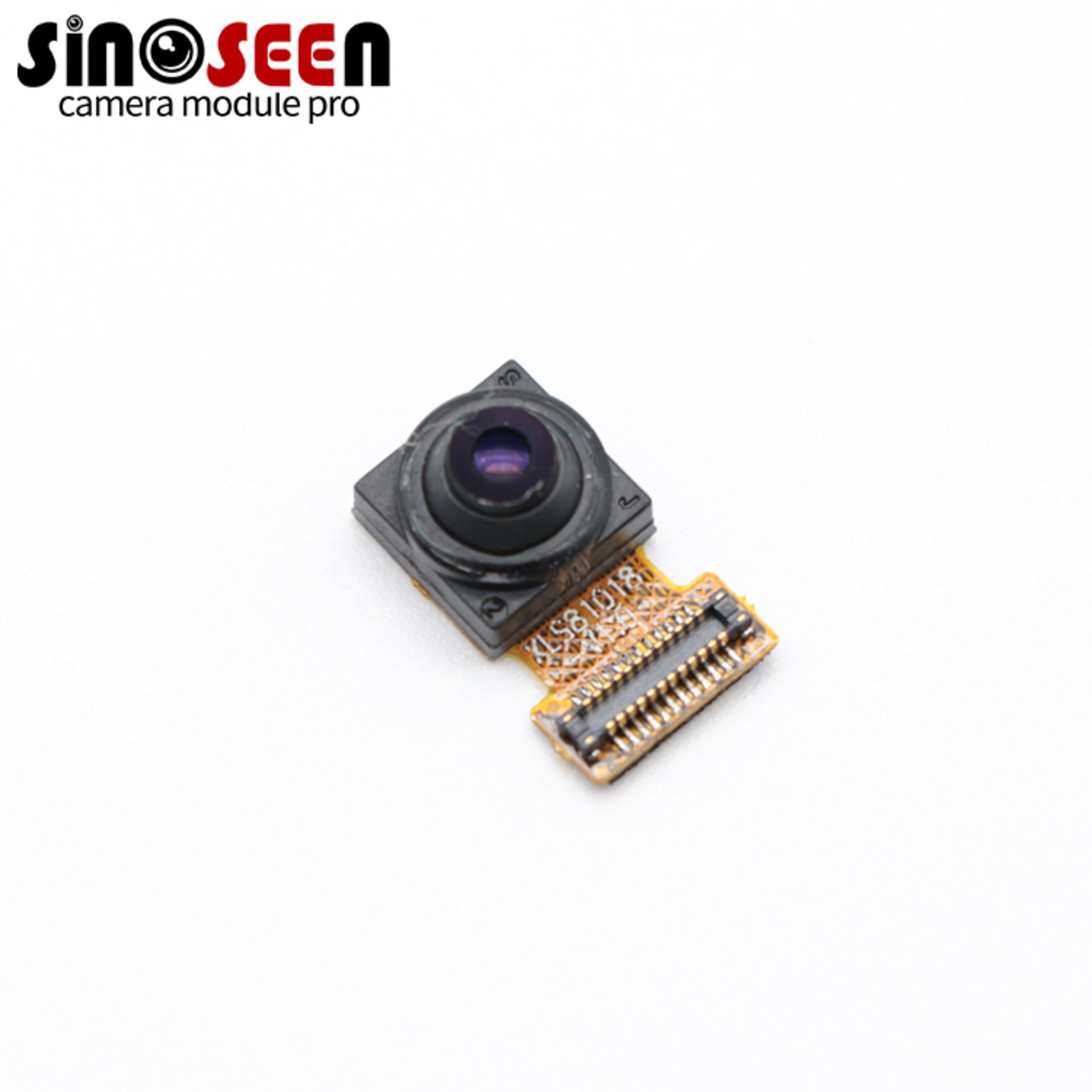
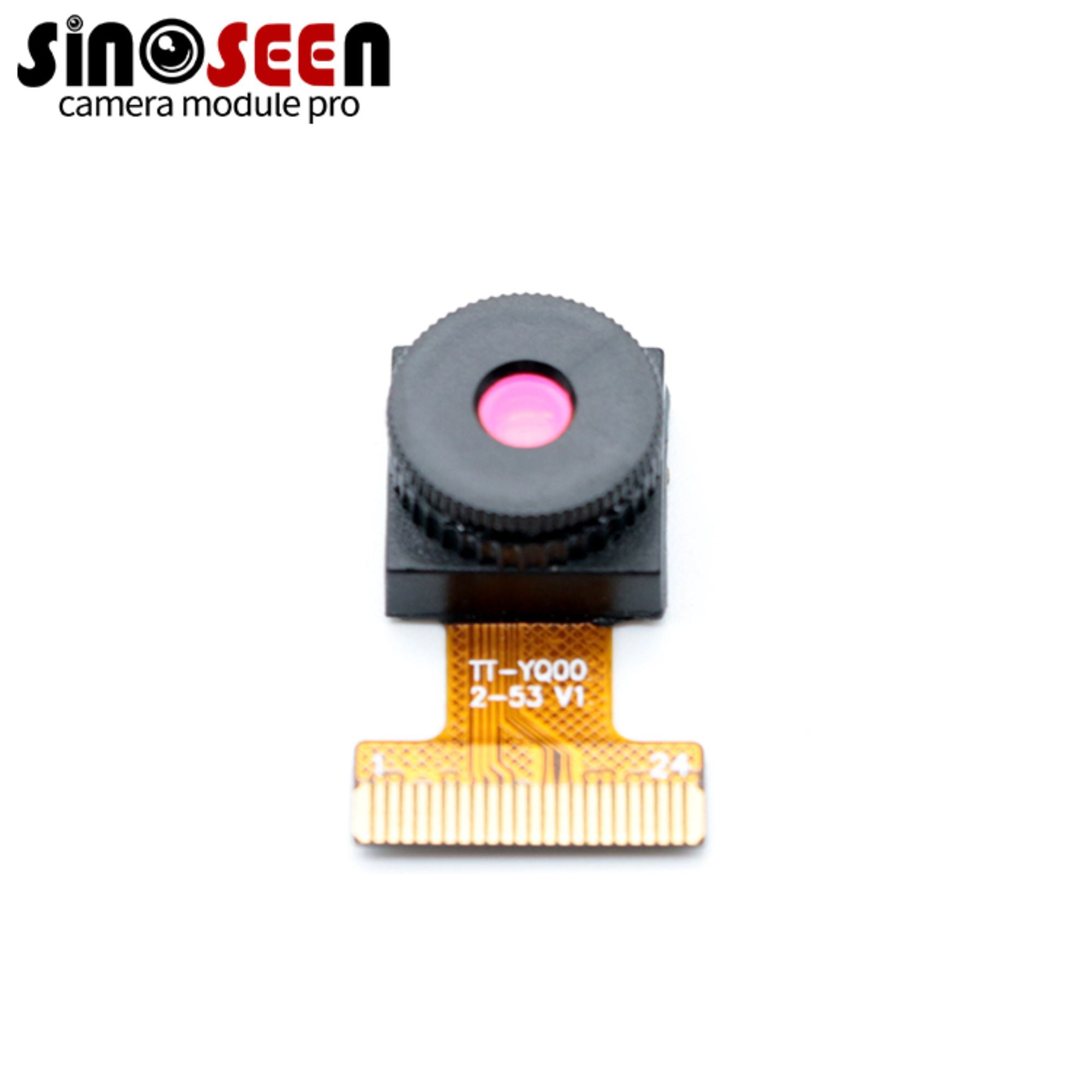
Sinoseen's OV9734 USB endoscope camera module, listed as model ZK-M3-V13, is a candidate for prototype evaluation in compact inspection equipment. The published configuration includes USB 2.0, fixed focus, 1280 x 720 at 30 fps, a foldable design, and an optional 60-degree field of view. These specifications provide a starting point; the final probe dimensions, lens configuration, and working distance still need to be validated against the target pipe.
Test the sample early with the actual computer or embedded host and the intended application. Confirm that the software can open the required video mode and save images at the expected resolution. The USB camera compatibility guide explains why an interface label alone does not establish operating-system or application compatibility.
Repeat testing with the planned cable routing. Move the probe through its normal operating range, disconnect and reconnect it, and run an extended preview. Look for video interruptions, USB resets, and unacceptable display delay. Agree on strain relief and the permitted bend radius before finalizing the mechanical design. A foldable construction does not, by itself, establish suitability for repeated flexing.
If liquids may be present, confirm the sealing requirements for the complete probe and cable assembly. A component specification does not establish an ingress-protection rating for the finished inspection tool. If the standard arrangement does not fit, discuss the required optics, board layout, and cable arrangement as a custom camera module project, subject to engineering review.
Use Sample Images to Define Production Acceptance
Use representative pipe sections for customer-facing sample images and retain the original captures. State the working distance, illumination, and capture resolution in each caption. Describe only what the image demonstrates. A single clear image does not establish crack-detection accuracy or show that a weld meets an acceptance standard.
For internal evaluation, retain a wider set of images covering glare, distance changes, and difficult surfaces. Before placing a production order, agree on the lens configuration, test conditions, and image acceptance criteria. Keep an approved reference sample and its images for comparison with later batches.
Include purchasing staff in configuration approval. Identify the camera board revision, lens, cable, and firmware version where applicable, and agree on how component substitutions will be communicated. A replacement lens can change the image even when its nominal field of view is unchanged. Re-evaluate a changed configuration against the approved reference before accepting it.
Frequently Asked Questions
Is 720p Enough for Pipe Inspection
It may be sufficient for locating joints and observing general surface condition at a suitable distance. Use actual sample images to confirm that the smallest feature relevant to the inspection is visible. Resolution alone does not establish whether the task can be completed reliably.
Does a USB Interface Guarantee Computer Compatibility
No. Confirm the delivered camera's video formats, driver requirements, and behavior with the intended software. The connector and interface name alone do not establish application compatibility.
Can This Module Measure Weld Defect Dimensions
Ordinary images can support visual observation. Reliable dimensional measurement requires suitable optics, calibration, and validated software. If defect dimensions are part of the inspection requirement, specify them separately and request a measurement solution rather than assuming the camera module provides one.
Should a Replacement Lens Be Tested Again
Yes. A different lens model or supplier may change sharpness, distortion, or focus behavior even when the stated field of view is the same. Compare the new configuration with the approved reference under the same conditions before accepting the next batch.
Discuss Your Industrial Endoscope Requirements
To evaluate a module for your inspection device, contact Sinoseen with the minimum opening, insertion depth, working distance range, required viewing direction, smallest feature to inspect, lighting plan, host platform, cable length, environmental conditions, and expected order volume. A drawing of the insertion path and representative pipe samples can help us assess the configuration and discuss feasible customization before sample approval.